How SCSI Works
Most home and small-office PCs use an IDE hard drive and have a PCI bus for adding components to the computer. But a lot of computers, particularly high-end workstations and older Apple Macintoshes, use the Small Computer System Interface (SCSI) bus to connect components, which may include:
- Hard drives
- Scanners
- CD-ROM/RW drives
- Printers
- Tape drives
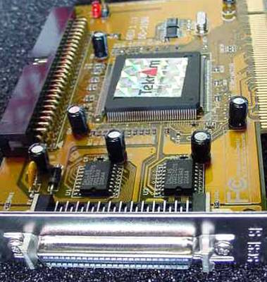
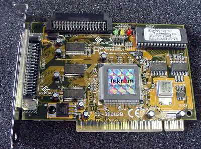
SCSI devices usually connect to a controller card like this one.
Basically, SCSI (pronounced "scuzzy") is a fast communications bus that allows you to connect multiple devices to your computer.
SCSI Basics
SCSI is based on an older, proprietary bus interface called Shugart Associates System Interface (SASI). SASI was originally developed in 1981 by Shugart Associates in conjunction with NCR Corporation. In 1986, a modified version of SASI that provided a beefier, open system was ratified by the American National Standards Institute (ANSI) as SCSI.
There are several benefits of SCSI:
- It's fast -- up to 160 megabytes per second (MBps).
- It's reliable.
- It allows you to put multiple devices on one bus.
- It works on most computer systems.
There are also some potential problems when using SCSI:
- It must be configured for a specific computer.
- It has limited system BIOS support.
- Its variations (speeds, connectors) can be bewildering.
There is no common software interface.
Some computers have a built-in SCSI controller, but most require an SCSI host-adapter card.
People are often confused by the different types of SCSI. You'll hear terms such as "Ultra," "Fast" and "Wide" used a lot, and sometimes in combinations. In the next section, you'll find out about the SCSI variations.
SCSI Types
The chart below shows a comparison of the many SCSI variations:
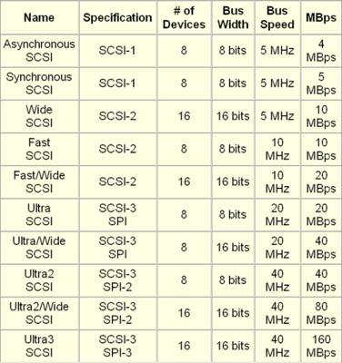
You will notice that the third column shows the number of devices that can be connected on the SCSI bus. In the next section, you'll learn more about SCSI devices and their IDs.
Identifiers
There are three components in any SCSI system:
- Controller
- Device
- Cable
The controller is the heart of SCSI. It serves as the interface between all of the other devices on the SCSI bus and the computer. Also called a host adapter, the controller can be a card that you plug into an available slot or it can be built right into the motherboard.
On the controller is the SCSI BIOS. This is a small ROM or Flash memory chip that contains the software needed to access and control the devices on the SCSI bus.
Usually, each device on the SCSI bus has a built-in SCSI adapter that allows it to interface and communicate with the SCSI bus. For example, an SCSI hard drive will have a small circuit board that combines a controller for the drive mechanism and an adapter for the SCSI bus. Devices with an adapter built in are called embedded SCSI devices.
Each SCSI device must have a unique identifier (ID). As you saw in the previous section, an SCSI bus can support eight or 16 devices, depending on the specification. For an eight-device bus, the IDs range from zero to 7, and for a 16-device bus, they range from zero to 15. One of the IDs, typically the highest one, has to be used by the SCSI controller, which leaves you capable of adding seven or 15 other devices.
With most SCSI devices, there is a hardware setting to configure the device ID. Some devices allow you to set the ID through software, while most Plug and Play SCSI cards will auto-select an ID based on what's available. This auto-selection is called SCSI Configured Automatically (SCAM). It is very important that each device on an SCSI bus have a unique ID, or you will have problems.
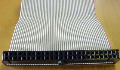
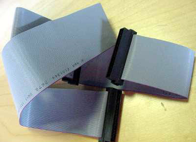
Internal SCSI devices connect to a 50-pin ribbon cable.
All of the variations in the SCSI specifications have added another wrinkle: There are at least seven different SCSI connectors, some of which may not be compatible with a particular version of SCSI. The connectors are:
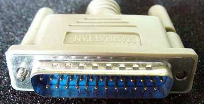
- DB-25 (SCSI-1)
- 50-pin internal ribbon (SCSI-1, SCSI-2, SCSI-3)
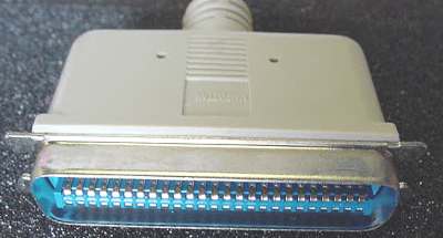
- 50-pin Alternative 2 Centronics (SCSI-1)
- 50-pin Alternative 1 high density (SCSI-2)
- 68-pin B-cable high density (SCSI-2)
- 68-pin Alternative 3 (SCSI-3)
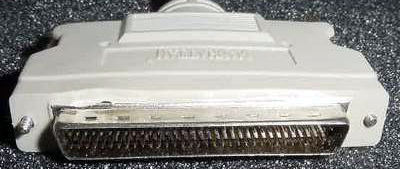
- 80-pin Alternative 4 (SCSI-2, SCSI-3)
No matter which version of SCSI you are using, or what type of connector it has, one thing is consistent -- the SCSI bus has to be terminated.
DB-25 SCSI connector
68-pin Alternative 3 SCSI connector
50-pin Centronics SCSI connector
Termination
Termination simply means that each end of the SCSI bus is closed, using a resistor circuit. If the bus were left open, electrical signals sent down the bus could reflect back and interfere with communication between SCSI devices and the SCSI controller. Only two terminators are used, one for each end of the SCSI bus. If there is only one series of devices (internal or external), then the SCSI controller is one point of termination and the last device in the series is the other one. If there are both internal and external devices, then the last device on each series must be terminated.
Types of SCSI termination can be grouped into two main categories: passive and active. Passive termination is typically used for SCSI systems that run at the standard bus clock speed and have a short distance, less than 3 feet (1 m), between the devices and the SCSI controller. Active termination is used for Fast SCSI systems or systems with devices that are more than 3 ft (1 m) from the SCSI controller.
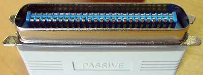
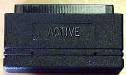
Some SCSI terminators are built into the SCSI device, while others may require an external terminator like this one.
Another factor in the type of termination is the bus type itself. SCSI employs three distinct types of bus signaling. Signalling is the way that the electrical impulses are sent across the wires.
- Single-ended (SE) - The most common form of signaling for PCs, single-ended signaling means that the controller generates the signal and pushes it out to all devices on the bus over a single data line. Each device acts as a ground. Consequently, the signal quickly begins to degrade, which limits SE SCSI to a maximum of about 10 ft (3 m).
- High-voltage differential (HVD) - The preferred method of bus signaling for servers, HVD uses a tandem approach to signaling, with a data high line and a data low line. Each device on the SCSI bus has a signal transceiver. When the controller communicates with the device, devices along the bus receive the signal and retransmit it until it reaches the target device. This allows for much greater distances between the controller and the device, up to 80 ft (25 m).
Low-voltage differential (LVD) - A variation on the HVD signaling method, LVD works in much the same way. The big difference is that the transceivers are smaller and built into the SCSI adapter of each device. This makes LVD SCSI devices more affordable and allows LVD to use less electricity to communicate. The downside to LVD is that the maximum distance is half of HVD -- 40 ft (12 m).
An active terminator
Both HVD and LVD normally use passive terminators, even though the distance between devices and the controller can be much greater than 3 ft (1 m). This is because the transceivers ensure that the signal is strong from one end of the bus to the other.
SCSI "Network"
SCSI devices inside the computer (internal) attach to the SCSI controller via a ribbon cable. The ribbon cable has a single connector at each end and may have one or more connectors along its length. Each internal SCSI device has a single SCSI connector.
SCSI devices outside the computer (external) attach to the SCSI controller using a thick, round cable.
Internal SCSI devices connect to a ribbon cable.
External SCSI devices connect using thick, round cables.
You have already read about the different connectors used on these external cables. The cable itself typically consists of three layers:
- Inner layer - This is the most protected layer. It contains the actual data being sent.
- Media layer - The middle layer contains the wires that send control commands to the device.
- Outer layer - This layer includes the wires that carry parity information, which ensures that the data is correct.
External devices connect to the SCSI bus in a daisy chain, which refers to the method of connecting each device to the next one in line. External SCSI devices typically have two SCSI connectors -- one is used to connect to the previous device in the chain, and the other is used to connect to the next device in the chain.
A good way to think of SCSI is as a tiny local area network (LAN). The SCSI controller is like the network router, and each SCSI device is like a computer on the network. The SCSI adapter built into each device is comparable to the Ethernet card in a computer. Without the adapter, the device can't communicate with the rest of the network. And just as the router in a LAN is used to connect the network to the outside world, the SCSI controller connects the SCSI network to the rest of the computer.
RAID
For general consumer use, SCSI has not achieved the same mass appeal as IDE. The expectation regarding SCSI was that the ability to add a large number of devices would outweigh the complexity of the interface. But that was before alternative technologies like Universal Serial Bus (USB) and FireWire (IEEE 1394) came into play.
In fact, the only mainstream desktop computer standardized on SCSI was the Apple Macintosh, and that was because of a design mistake. The original Mac was a closed system, which means that there were no expansion slots or other means to easily add extra components. As the Mac grew in popularity, users began to clamor for some way to upgrade their system. Apple decided to add a built-in SCSI controller with an external SCSI port as a way to enable expansion of the system. Until recently, virtually every Mac has contained onboard SCSI. But with the rise of USB and Firewire, Apple has finally removed SCSI as a standard feature on most of its systems.
Where you commonly see SCSI is on servers and workstation computers. The main reason for this is RAID. Redundant array of independent disks (RAID) uses a series of hard drives to increase performance, provide fault tolerance or both. The hard drives are connected together and treated as a single logical entity. Basically, this means that the computer sees the series of drives as one big drive, which can be formatted and partitioned just like a normal drive.
Performance is enhanced because of striping, which means that more than one hard drive can be writing or reading information at the same time. The SCSI RAID controller determines which drive gets which chunk of data and sends the appropriate data to the appropriate drive. While that drive is writing the data, the controller sends another chunk of data to the next drive or reads a chunk of data from another drive. Simultaneous data transfers allow for faster performance.
Fault tolerance, the ability to maintain data integrity in the event of a crash or failure, is achieved in a couple of ways. The first is called mirroring. Basically, mirroring makes an exact duplicate of the data stored on one hard drive to a second hard drive. A RAID controller can be set to automatically send two hard drives the exact same data. To avoid potential complications, both drives should be exactly the same size. Mirroring can be an expensive type of fault tolerance since it requires that you have twice as much storage space as you have data.
The more popular method of fault tolerance is parity. Parity requires a minimum of three hard drives, but will work with several more. What happens is that data is written sequentially to each drive in the series, except the last one. The last drive stores a number that represents the sum of the data on the other drives.
Digital video is another prime example of the right time to use SCSI. Because of the demanding storage and speed requirements of full-motion, uncompressed video, most video workstations use a SCSI RAID with extremely fast SCSI hard drives.
As you can see, SCSI is probably going to be around for some time. Whether it's right for you depends on your needs and applications.


2 Comments:
Nice photos ;-)
Haha, while surfing blogexplosion, I found your blog
Post a Comment
<< Home